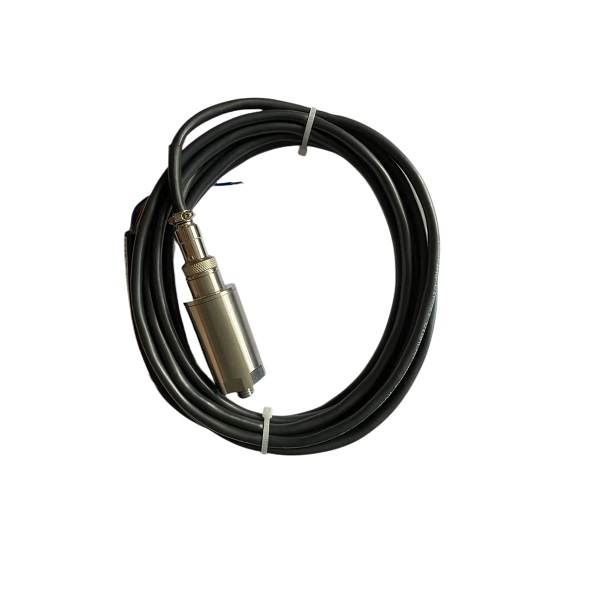
Technical parameters
The Technical parameters of Vibration Transmitter JM-B-35:
| Frequency range | 10 ~ 200Hz |
| Measurement range | 0~200um or 0~500um;
0~20mm/s or 0~40mm/s |
| Linear error | ≤±1%FS |
| Load resistance | ≤ 750 Ω (DC24V power supply) |
| Output current | DC 4 ~ 20mA (constant current) |
| Working environment | - 10 ~ 75 ℃ |
| Power supply | DC 24V |
| Measurement methods | vertical、horizontal and axial |
| Fixed screw hole | M10 x 1.5 x 10 (depth) |
| Dimensions | 44x 91 (mm) |
Installation and use
This Integrated Bearing Vibration Transmitter JM-B-35 should be installed in a clean, dry and non-corrosive gases occasion with environment temperature - 10 ~ 70 ℃. Don’t install in strong electric field, strong magnetic interference and strong shock or vibration places.
Please use the shielded cable during transmission progress of transmitter to computer system. One end of the transmitter is aerial reticulate shielding layer and another end of the shielding wire connects the ground wire.
Notes
1. The Integrated Bearing Vibration Transmitter JM-B-35 adopts sealing structure. It can’t be use when the environment temperature is more than 70 ℃. Don’t install the transmitter in a place which vulnerable to rain.
2. Installation location: in principle, it should be installed in the position of vibration measurement in ordinary operation. Tap a M16 x 1.5 standard wire with 10mm in depth on the tile cover. Use the M16 type screws in sensor bottom to fix the transmitter in the measured spot. When installation, make sure the transmitter is in horizontal or vertical to ensure that the sensor can work normally.
3. The Integrated Bearing Vibration Transmitter JM-B-35 output is aerial grounding. The shielding layer cannot connect with the transmitter, including shell, so it can effectively avoid interference.
4. Output current lead can be arbitrary connected in series between positive wire and negative wire. The transmitter power input is non-polarity.
- English
- French
- German
- Portuguese
- Spanish
- Russian
- Japanese
- Korean
- Arabic
- Irish
- Greek
- Turkish
- Italian
- Danish
- Romanian
- Indonesian
- Czech
- Afrikaans
- Swedish
- Polish
- Basque
- Catalan
- Esperanto
- Hindi
- Lao
- Albanian
- Amharic
- Armenian
- Azerbaijani
- Belarusian
- Bengali
- Bosnian
- Bulgarian
- Cebuano
- Chichewa
- Corsican
- Croatian
- Dutch
- Estonian
- Filipino
- Finnish
- Frisian
- Galician
- Georgian
- Gujarati
- Haitian
- Hausa
- Hawaiian
- Hebrew
- Hmong
- Hungarian
- Icelandic
- Igbo
- Javanese
- Kannada
- Kazakh
- Khmer
- Kurdish
- Kyrgyz
- Latin
- Latvian
- Lithuanian
- Luxembou..
- Macedonian
- Malagasy
- Malay
- Malayalam
- Maltese
- Maori
- Marathi
- Mongolian
- Burmese
- Nepali
- Norwegian
- Pashto
- Persian
- Punjabi
- Serbian
- Sesotho
- Sinhala
- Slovak
- Slovenian
- Somali
- Samoan
- Scots Gaelic
- Shona
- Sindhi
- Sundanese
- Swahili
- Tajik
- Tamil
- Telugu
- Thai
- Ukrainian
- Urdu
- Uzbek
- Vietnamese
- Welsh
- Xhosa
- Yiddish
- Yoruba
- Zulu
- Kinyarwanda
- Tatar
- Oriya
- Turkmen
- Uyghur


