

During the operation of the steam turbine, the gap between the rotor and the stator is one of the core parameters to ensure the safety of the unit. Once the axial displacement exceeds the safety threshold, the rotor and stator components may collide, resulting in serious accidents such as blade breakage and bearing damage. To avoid such risks, modern steam turbines generally adopt the linkage mechanism of eddy current axial displacement sensor and trip protection system (ETS). Below we take the WT-0112-A90-B00-C01 eddy current sensor as an example to introduce how it can achieve real-time response to axial displacement overrun through high-precision displacement monitoring and coordinated with the ETS system, thereby ensuring the safe operation of the unit.
I. Sensor principle and displacement monitoring technology
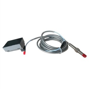
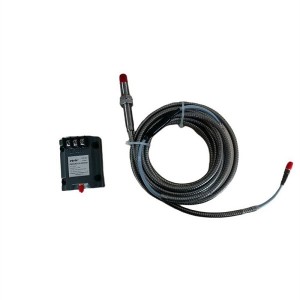
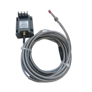
The eddy current axial displacement sensor works based on the principle of electromagnetic induction. The WT-0112-A90-B00-C01 sensor consists of a probe, an extension cable and a preamplifier. The internal coil of the probe generates an alternating magnetic field under the action of a high-frequency oscillating current. When the distance between the sensor and the surface of the metal rotor being measured changes, the magnetic field induces eddy currents on the metal surface, causing the equivalent impedance of the coil to change, which in turn affects the Q value of the oscillation circuit. This change is converted into a voltage signal by the preamplifier, and after linearization processing, it can accurately reflect the real-time gap between the rotor and the sensor.
The sensor adopts non-contact measurement to avoid the influence of mechanical wear on accuracy, and has strong anti-interference ability, suitable for harsh working conditions such as high temperature and high pressure. Its measurement range usually covers -1.0mm to +1.0mm, and its sensitivity can reach micron level, ensuring that the warning is triggered as soon as the axial displacement exceeds the safe range.
II. ETS system function and protection logic
The turbine trip protection system is the “last line of defense” for the safe operation of the unit. Its core function is to monitor key parameters in real time. When the parameters exceed the preset threshold, the unit is forced to shut down by closing all steam inlet valves, cutting off the power supply and other compulsory measures. In axial displacement monitoring, the linkage logic between ETS and sensors usually includes the following links:
Signal acquisition and transmission: The eddy current sensor WT-0112-A90-B00-C01 transmits the axial displacement data to the input module of ETS through an extension cable. The signal needs to be filtered, amplified and processed to eliminate electromagnetic interference and ensure data accuracy.
Threshold judgment and logical operation: The ETS system presets the normal operating range and emergency shutdown threshold of the axial displacement. When the sensor signal exceeds the shutdown threshold, the system starts the “three out of two” or “two out of one” redundant logic to avoid malfunction caused by a single sensor failure.
Protection command triggering: After confirming that the displacement exceeds the limit, ETS releases the safety oil pressure by controlling the solenoid valve group, so that the main steam valve and the regulating valve are quickly closed, and the generator is decoupled, and finally the unit is shut down.
III. Key links of the linkage mechanism
1. Sensor installation and calibration
The installation position of the axial displacement sensor WT-0112-A90-B00-C01 needs to be precisely aligned with the sensitive area of the rotor axial displacement, which is usually located near the thrust bearing. During installation, it is necessary to ensure that the initial gap between the probe and the rotor surface meets the design requirements, and adjust the signal output through the calibration tool to make it linearly correspond to the actual displacement value. In addition, the sensor bracket must have sufficient rigidity to avoid vibration interference with signal stability.
2. Signal redundancy and anti-interference design
To improve system reliability, steam turbines are usually equipped with two or three sets of eddy current sensors WT-0112-A90-B00-C01 to form a redundant measurement network. The ETS system adopts the “three out of two” logic, that is, the shutdown command is executed only when at least two sensors trigger the over-limit signal at the same time. At the same time, the sensor signal line and the power cable need to be laid independently, and a shielding layer should be added to prevent misjudgment caused by external electromagnetic interference.
3. Dynamic response and delay control
Axial displacement over-limit may be caused by sudden failure or progressive abnormality. The ETS system needs to balance the timeliness of protection action and the stability of the unit. For example, when the axial displacement sensor detects that the displacement increases at a rate exceeding the threshold by 20%, the system can trigger an early warning; if the displacement continues to grow to the shutdown threshold, the shutdown command is output and executed within 1 second.
IV. Key points for system optimization and maintenance
Although the linkage mechanism between the eddy current sensor WT-0112-A90-B00-C01 and ETS is highly reliable, it needs to be continuously optimized through the following measures:
Regular calibration and calibration: The sensor needs to be calibrated for zero point and range every quarter to ensure measurement accuracy.
Signal loop inspection: Regularly test the insulation of the signal line to check for grounding or short circuit faults.
Logic loop verification: Verify the response time and action accuracy of the ETS protection logic through simulation tests.
Data recording and analysis: Use the online monitoring system to accumulate displacement change trend data and identify potential risks in advance.
When looking for high-quality, reliable eddy current sensors, YOYIK is undoubtedly a choice worth considering. The company specializes in providing a variety of power equipment including steam turbine accessories, and has won wide acclaim for its high-quality products and services. For more information or inquiries, please contact the customer service below:
E-mail: sales@yoyik.com
Tel: +86-838-2226655
Whatsapp: +86-13618105229
Yoyik offers various types of spare parts for steam turbines, generators, boilers in power plants:
Case Expansion Monitor DF9032
analog rpm gauge WZ-3C
pressure switch CMS-I 0.35MPa
Bimetal Thermometer WSS-361
6KV SWITCHGEAR VEP VEP12T4050D11P27W
external hydraulic cylinder position sensor 5000TDZ-A
speed mornitor ZKZ-3T
speed sensor WT0180-A08-B00-C08-D50
Voltage meter SF96 C2 0-500V
Sensor K156.33.42.08G01
Electric heating rod ZJ-20-T6
ALARM HORN; BC-110
High Voltage fuse N2-24/0.5
Relay CM-ESN
PRESSURE SWITCH BH-013011-013
Magnetoresistive speed probe SMCB-01-A10-B090-C0S-D02-E02
Analog Input Module HAI805
linear movement sensor TDZ-1E-03
ZW185 Arc Chute 1SFN164710R1000
oil level indicator sensor UHZ-618C17
Limit Switch D4A-4510N
Brake ZD280-E
4 CHANNEL RELAY MODULE 3500/32
Speed probe CS-1-G-100-04-01
Electric actuator RPK-05
LVDT sensor 4000td-xc3
Eddy current sensor with probe 8300-A25-B90
Magnetic Resistance Speed Sensor SZCB-02-B117
RTD WZP2-210
Temperature Sensor TE-1203B wzpk2-736
COAL VALVE GT212707
SENSOR DIFFERENTIAL EXPANTION PROBE PR6426/010-040+CON 021/916-160
Signal conditioning module analog quantity HSDS-30/FM
Post time: Apr-25-2025
-

Globe valve SHV25
-

LVDT Position Sensor HL-6-250-15
-

APH Fan oil cooler GLC3-41.6
-

BFP lube filter QF9732W25HPTC-DQ
-

Selector 2-position Option switch ZB2BD2C
-

Hydraulic lubricating oil station filter ZNGL02...
-

CWY-DO Steam Turbine Eddy Current Sensor
-

Oil purifier circulating filter element HC8314F...
-

Generator Hydrogen sealing Sealant D25-75
-

Steam Turbine EH Oil System Servo Valve 072-559A
-

TDZ-1E series linear displacement transducer LV...
-

Copper Washers FA1D56-03-21