

In the field of industrial automation and precision machinery, LVDT (Linear Variable Differential Transformer) displacement sensors have become the core components for displacement monitoring of key components of steam turbines due to their high-precision and non-contact measurement characteristics. Among them, LVDT sensor K156.33.31.04G01 is widely used in steam turbine valve stem displacement detection due to its compact design and high reliability. However, the coaxiality deviation between the sensor core and the valve stem directly affects its measurement accuracy, especially when the deflection error exceeds ±0.5°, it will cause significant nonlinear output and threaten the stability of the system.
I. Coaxiality control: the necessity of precise matching of LVDT core and valve stem
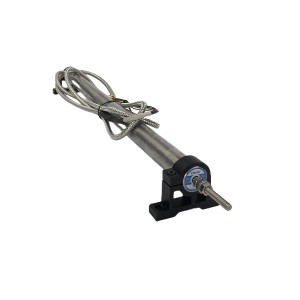
The core working principle of LVDT displacement sensor K156.33.31.04G01 is based on electromagnetic coupling changes. Its internal structure includes a movable rod-shaped core and a fixed coil assembly. When the core moves with the valve stem, the magnetic flux distribution between the coils changes, and the displacement is converted into an electrical signal through differential output. This process requires that the motion trajectory of the core and the valve stem is strictly coaxial to ensure the uniformity of magnetic field coupling. If there is a deviation between the two, the iron core will deviate from the central axis of the coil during movement, resulting in an asymmetric magnetic circuit, which in turn causes abnormal fluctuations in the induced voltage of the secondary coil.
As a key component of power transmission, the displacement accuracy of the turbine valve stem directly affects the load control and safe operation of the unit. The installation environment of the K156.33.31.04G01 displacement sensor is usually accompanied by high temperature, vibration and complex electromagnetic interference, which further amplify the potential risk of coaxiality deviation. Therefore, ensuring the coaxiality of the iron core and the valve stem through precise installation and dynamic calibration is the basis for ensuring the linearity of the sensor output.
II. Installation and calibration technology: a systematic solution to achieve coaxiality
The coaxiality control of the sensor and the valve stem needs to be coordinated from three aspects: mechanical design, installation process and calibration process. First, in the mechanical structure design, high-precision bearings or guide devices are required to constrain the movement direction of the valve stem to prevent it from being offset due to external force or deadweight. The housing of the K156.33.31.04G01 displacement sensor is usually equipped with an adjustable bracket, which allows the flatness error of the mounting surface to be compensated by fine-tuning screws to ensure the geometric alignment of the sensor axis and the valve stem axis.
During the installation process, the operator needs to follow a standardized process:
• Reference positioning: Fix the sensor bracket to the turbine base, and measure the parallelism between the mounting surface and the valve stem axis by a laser alignment instrument or a dial indicator. The error must be controlled within ±0.05mm.
• Dynamic simulation calibration: After the initial connection between the sensor and the valve stem, apply a simulated load and slowly move the valve stem. The symmetry and linearity of the output signal are monitored in real time through an oscilloscope. If signal distortion occurs, the bracket position needs to be adjusted until the output curve returns to the ideal state.
• Anti-loosening and sealing treatment: In order to cope with long-term vibration, the connection thread between the sensor and the valve stem needs to use high-strength locking glue, and a shock-absorbing gasket is added to the contact surface to prevent axis deviation caused by loosening.
III. Nonlinear influence of skew error: System response under ±0.5° threshold
When the coaxiality deviation between the core and the valve stem exceeds ±0.5°, the sensor output will show significant nonlinear characteristics. This angle threshold is derived from the geometric constraints of the linear working range of the LVDT position sensor K156.33.31.04G01 and the core motion trajectory. It is specifically manifested in the following three points:
1. Signal amplitude distortion
Skewing causes the angle between the LVDT core and the central axis of the coil to increase, causing the magnetic flux in some coil areas to drop sharply, while the other side is enhanced due to the reduction of magnetic resistance. This asymmetric distribution will change the ratio of the induced electromotive force of the secondary coil, and the final output voltage will deviate from the ideal linear relationship. For example, when the skew angle is 0.6°, the output signal may show an asymmetric sawtooth waveform in the positive and negative strokes, resulting in an error of more than ±5% in the displacement measurement value.
2. Frequency response degradation
When the high-frequency vibration of the valve stem (such as turbine rotor oscillation) is superimposed on the coaxiality deviation, the friction resistance between the core and the coil will fluctuate with the change of displacement direction. This dynamic friction will cause high-frequency noise to be superimposed on the sensor output, reducing the signal-to-noise ratio. Experimental data show that a 0.8° deflection can increase the peak-to-peak noise of the output signal by 30%, interfering with the control system’s ability to capture small displacement changes.
3. Long-term stability decreases
Continuous deflection will accelerate the wear of the core and coil skeleton. The contact between the core edge and the coil insulation layer may cause partial discharge, eventually leading to coil short circuit or insulation failure. A case study of a power plant showed that after 12,000 hours of operation, the primary coil resistance of the LVDT with a long-term deflection of 0.7° rose to twice the rated value, forcing the unit to shut down and replace the sensor, resulting in several days of unplanned downtime losses.
The core value of the LVDT displacement sensor K156.33.31.04G01 in turbine displacement monitoring comes not only from its high-precision displacement-voltage conversion capability, but also from the precise control of the coaxiality of the core and the valve stem. Through systematic installation calibration, dynamic compensation and full life cycle maintenance, the deflection error can be strictly controlled within ±0.5° to avoid the damage of nonlinear output to the control accuracy of the unit.
When looking for high-quality, reliable LVDT Displacement Sensors, YOYIK is undoubtedly a choice worth considering. The company specializes in providing a variety of power equipment including steam turbine accessories, and has won wide acclaim for its high-quality products and services. For more information or inquiries, please contact the customer service below:
E-mail: sales@yoyik.com
Tel: +86-838-2226655
Whatsapp: +86-13618105229
Yoyik offers various types of spare parts for steam turbines, generators, boilers in power plants:
miran linear position sensor TDZ-1-100
Guide blade opening DYK-II-1013
MODUL MVC196E-01
GAS TRANSMITTER LH1500
PRESSURE SWITCH RC778NZ090-H
IP Site Connect XiR8668Ex
Temperature Sensor WZPK2-240
Sensor+Module Transmitter Vibration 8300-A08-B90 ZH30103-A00-B08-CI0-D01-E00I
speed sensor DSD1820.19S22HW
linear transducer sensor TDZ-1E-31
Booster Relay YT-300N1
SENSOR TEMPERATURE RTD WZPM2-201Y-X2
Intelligent Rotary Speed Monitor QBJ-3C/Q
Thermal resistor 8100.5000248096
Stainless manometer YJTF-100ZT
Displacement Sensors BIW1-E310-M0075-P1-S115
THERMOCOUPLE 158.91.10.01+2
THERMAL RESISTANCE SENSOR WZPM2-08-102-M18-S
UPS SURT5000UXICH
Brush Holder HDK-3
pressure transducer types CMS-50
BELT TAKE UP PULLEY GT2150307
MICRO SWITCH.12A/125 VDC. TYPE SHORT HINGE ROLLER LEVER. Z-15GW22-B
Power Supply XGP-ACF2
Thyristor DCR 1006SF2626
lvdt displacement transducer TDZ-1E-33
Hydrostatic Level Transmitter MIK-P261
SPARK GAP TUBE XDH8-80C
hydraulic pressure sensor 396723-SA6B2530-0INHG
VELOMITOR PIEZO VELOCITY SENSOR 330500-00-01
Presure transmitting controller MPM484ZL
AUXILIARY RELAY JZS-7/2403 (XJZS-2403)
zero speed probe D-100-02-01
Eddy Current Sensors DFA0180-RE022-323TQ
Post time: Apr-28-2025
-

Hydraulic oil filter element SDGLQ-25T-16
-

Hydraulic oil system filter element FAX 250*10
-

HDJ892 Generator hydrogen sealing slot sealant
-

Double gear Pump GPA2-16-16-E-20-R6.3
-

Rotational Speed Monitor MSC-2B
-

Stator coil surface HR anti-corona varnish 1244
-

Generator Hydrogen sealing Sealant D20-75
-

Online Hydrogen Leak Detector KQL1500
-

generator stator cooling water filter element K...
-

Generator hydrogen cooling system safety valve ...
-

WFF-125-1 Generator stator cooling water filter...
-

Generator stator cooling water filter SWFY3 DN100