

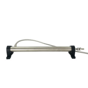
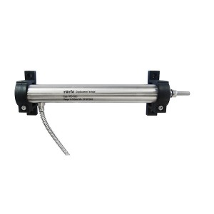
In the steam turbine control system, the precise control of the main steam valve is the core link to ensure the safety and stable operation of the unit. As a key element for valve position feedback, the measurement accuracy of the LVDT displacement sensor K156.33.42.08G01 directly affects the real-time monitoring and closed-loop control of the valve opening. In order to ensure that the movement direction of the LVDT core is completely coaxial with the displacement of the main steam valve stem, the design and installation accuracy of the mechanical limit device are crucial.
1. Coaxial control principle of mechanical limit device
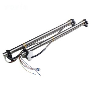
The displacement synchronization of the core of the LVDT sensor K156.33.42.08G01 and the main steam valve stem depends on a precise mechanical limit system. The system uses a multi-level constraint structure to ensure that the core only moves along the axial direction of the valve stem to avoid lateral displacement or tilt. The core components include guide keyways, slider guides and fixed brackets, which work together to form a rigid constraint path.
First, the K156.33.42.08G01 sensor body is fixed to the valve body or bracket by flanges or threads, and its axis must be strictly aligned with the center line of the valve stem. The guide keyway is designed as a long hole structure along the length of the valve stem, in which the core or connecting rod is embedded, allowing only linear motion. This mechanical constraint effectively limits the radial displacement of the core and prevents displacement caused by vibration or external force. Secondly, the slider guide device further strengthens the coaxiality. The slider usually adopts a combination structure of a wave-shaped cover plate and a guide bump, and forms an adaptive guide path through the contact between the elastic unit and the coil skeleton. When the core moves with the valve stem, the guide bump slides along the keyway to ensure that the motion trajectory coincides with the valve stem axis. In addition, some designs also include numerical scales and rotating columns to facilitate fine-tuning of the position during installation so that the initial zero position of the core is completely consistent with the mechanical zero position of the full stroke of the valve stem.
The material selection and processing accuracy of the mechanical limit device are also critical. The coil skeleton and guide components are mostly made of high-rigidity alloys or stainless steel to resist deformation under high temperature, high pressure and vibration environments. The gap between the core and the keyway must be strictly controlled at the micron level to ensure frictionless movement and avoid dynamic deflection caused by excessive gaps. This precision design enables the LVDT output signal to form a highly linear mapping with the valve stem displacement, providing a reliable feedback reference for the control system.
2. Interlocking effect of installation offset on the control system
Although the mechanical limit device can effectively constrain the direction of the core movement, the deviation during the installation process may still cause system errors. The installation offset is mainly divided into three categories: axial, radial and angular deviations. The interference mechanism of the control logic is as follows:
Axial offset: If there is a slight axial misalignment between the LVDT sensor K156.33.42.08G01 body and the valve stem axis, the connecting rod between the core and the valve stem may bend due to uneven force. This deformation will change the initial position of the core in the coil, resulting in zero drift. For example, when the valve stem is in the closed state, the core may have deviated from the center of the coil. At this time, the system will misjudge that the valve is open, triggering the compensation action of the control module. In long-term operation, such deviations may accumulate, resulting in the actual valve opening deviation from the command signal, and in severe cases, triggering a protective shutdown.
Radial offset: Radial deviation is manifested as the LVDT axis and the valve stem axis are not in the same plane. At this time, the movement trajectory of the iron core will include a lateral component. Although the mechanical limit can limit its displacement, the friction between the iron core and the inner wall of the coil will increase wear and reduce the life of the sensor. The more direct impact is that the lateral displacement of the iron core will change the magnetic coupling strength between the coils, causing nonlinear distortion of the output signal. For example, when the valve is opened to 50% of the stroke, the LVDT sensor may cause the output voltage to increase or decrease abnormally due to radial offset. The control system adjusts the actuator accordingly, which may cause the valve to be over-opened or under-opened, destroying the stability of the steam flow.
Angle deviation: If the sensor K156.33.42.08G01 forms a small angle with the valve stem during installation, the movement of the iron core will include a rotational component. The output signal of the LVDT is based on the linear change of the iron core displacement, and the rotation will cause the relative position of the iron core and the coil to change periodically, generating high-frequency noise or signal fluctuations. In closed-loop control, this fluctuation will be mistaken for the dynamic response deviation of the valve, resulting in frequent adjustments of the PID regulator and even system oscillation. For example, under the condition of rapid load increase, the valve needs to respond to the command quickly. The angle deviation may cause the control system to over-correct, resulting in drastic fluctuations in the valve opening, threatening the stability of the unit.
In addition, the installation offset may also indirectly affect the environmental adaptability of the sensor. For example, radial offset causes the core to contact the coil, which may accelerate the aging of the insulation material at high temperature or cause the coil to short-circuit in a vibrating environment. These faults will directly cut off the displacement feedback signal, forcing the control system to switch to the backup sensor or trigger a safe shutdown, increasing the risk of unplanned shutdown.
3. Fault tolerance and compensation of the control system for installation deviation
To cope with the potential risks brought by installation deviation, modern steam turbine control systems usually adopt redundant design and intelligent algorithms. For example, the redundant configuration of dual LVDT sensors can compare the difference between the two signals, automatically isolate the faulty sensor when the deviation exceeds the threshold, and issue an early warning. In addition, the software compensation strategy corrects the initial zero position and linearity errors through online calibration. For example, in the full stroke test of the valve, the control system records the correspondence between the sensor output and the mechanical stroke, and establishes a mapping table to offset the impact of installation deviation.
However, such compensation measures have limitations. For dynamic deviations (such as real-time displacement fluctuations caused by vibration), the response speed of the software algorithm may lag behind physical changes, resulting in control delays. Therefore, installation accuracy is still the fundamental guarantee of system reliability. On-site installation must strictly follow process specifications, including the use of laser centering instruments to calibrate the axis, pre-tightening torque to control bolt torque, and full-stroke simulation tests before operation.
The mechanical limit device of the turbine main steam valve LVDT displacement sensor K156.33.42.08G01 strictly constrains the core movement to the valve stem axis direction through a precise guide structure, providing stable and reliable displacement feedback for the control system. Although the installation offset can be partially alleviated by redundancy and compensation strategies, the control deviation caused by it may still pose a threat to the safety of the unit. Therefore, from design selection to on-site installation, each link must be based on high precision, combined with mechanical constraints and digital calibration to achieve full life cycle reliability of displacement measurement.
When looking for high-quality, reliable LVDT displacement sensors, YOYIK is undoubtedly a choice worth considering. The company specializes in providing a variety of power equipment including steam turbine accessories, and has won wide acclaim for its high-quality products and services. For more information or inquiries, please contact the customer service below:
E-mail: sales@yoyik.com
Tel: +86-838-2226655
Whatsapp: +86-13618105229
Yoyik offers various types of spare parts for steam turbines, generators, boilers in power plants:
Universal joint UK-77-M6-M6
Conveyor deviation switch TPKY-5X20/35
Manual Inductor CT1-400A
Speed probe CS-3-M16-L220
PROBE FOR DIFFERETIAL EXPANSION (PROXIMITY SENSOR) CWY-DO-02-04-050
Vibration Module 6/317A
TIMER NJS1-2Z
sensor K WRKK2-221
Pressure reducing valve PQ-235C
Shaft vibration probe 111-402-000-013-A1-B1-C042-D000-E010-F0-G000-H10
Embedded touch screen HSDS-30/C
DIODE R6W12033V0
Extension cable 330130-080-00-00
speed probe 1071/2
6KV TRANSFORMER PROTECTION RELAY NEP 983
Indication AD16-22C/R32S/AC380V
TEMPERATURE SENSOR WZPK2-33G
Transducer DBSQ 131
pt100 dual element WZP2-221
Thermocouple WRNK2-331
POSITIONER EPOS 1436
ELECTRICAL LINEAR VARIABLE DIFFERENTIAL TRANSFORMER TDZ-1B-02
RTD WZP-316T
PLC VIBRATION MODULE HY-6000VE/11
PRESSURE TRANSDUCE TYPE CAREBAR T P31
Large bolt electric heater ZJ-20-813
Belt Sways Switch ZCKJ4-E05-Y53
Bimetal Thermometer WSS-561W
transmitter XCBSQ-02-250-02-01
Dual color water level gauge for Steam Drum B49H-10
Board for valve ME8.530.014
bolts heater 1.2311(4)-φ21X1000
pressure controller QYJ-10Kpa
board ME8.530.014 V2_0
Digital Temperature Indicator XMZ-155
Post time: Apr-24-2025
-

EH oil online filter machine fine filter JLX-30...
-

GJCF-15 APH Gap Control system Signal Transmitter
-

Filter element MZFP-32-118 mesh
-

EH oil main pump skeleton oil seal TCM589332
-

Steam Turbine Excitation System CPU board PCA-6...
-

Hydraulic oil Pump Filter Element SDGLQ-25T-32
-

LVDT Position Sensor HL-6-150-15
-

EH oil regeneration Alumina Filter 30-150-219
-

Recycle pump washing oil filter DP1A401EA01V/-F
-

Generator Hydrogen sealing Sealant D25-75
-

BFPT LUBE oil filter element RLFDW/HC1300CAS50V02
-

Pressure Switch ST307-V2-350-B