

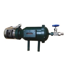
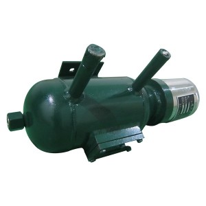
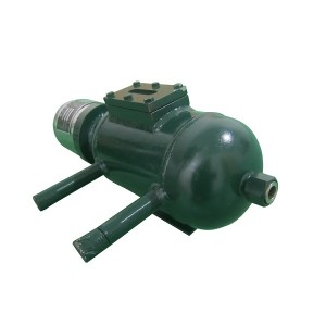
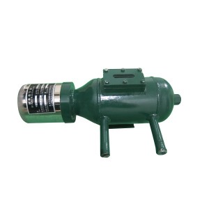
In modern power systems, the safe operation of generators is directly related to the stability of the entire power grid. As the “guardian” of the generator’s hydrogen oil-water system, the accuracy and reliability of the oil-water alarm are crucial. However, the operating environment of the generator is complex, and electromagnetic interference and mechanical vibration often become “invisible killers” that affect the performance of the alarm. Combined with industry practical experience, this article deeply analyzes the installation skills of the OWK-III-G oil-water alarm to help users achieve the “double insurance” of electromagnetic protection and vibration control.
1. Environmental assessment and planning before installation
1.1 Electromagnetic environment analysis
The internal magnetic field strength of the generator can reach more than 1000 Gauss. If the alarm is installed close to the stator winding or excitation system, it is easy to cause signal distortion. It is recommended to give priority to relatively weak magnetic field areas such as near the hydrogen cooler and below the air cooling island. At the same time, it is necessary to avoid strong electromagnetic equipment such as DCS control cabinets and inverters, and use metal shielding covers for isolation when necessary.
1.2 Vibration source identification
When the generator is running, it will generate mechanical vibrations of 0.5-5mm/s. If the alarm is directly fixed on the generator body or pipeline, long-term vibration will cause the sensor to loosen and the line to break. It is recommended to measure the vibration value of key parts through a vibration analyzer, and give priority to installing in areas with a vibration amplitude of <2mm/s.
1.3 Pipeline layout optimization
The sampling tube of the alarm needs to be connected to the generator inlet/return oil (water) port to form a closed loop. According to the practical experience of the website, the single-tube sampling system should avoid opening the upper and lower cock doors at the same time. It is recommended to use a “U-shaped bend” design to reduce the risk of hydrogen leakage. At the same time, the length of the sampling tube should be controlled within 10 meters to avoid the vibration effect caused by the long pipeline.
2. Five core skills of electromagnetic interference protection
2.1 Shielding and grounding technology
Shielded cable: Use twisted pair or metal armored cable, one end of the shielding layer is grounded, and the other end is connected to the alarm housing through a 3MΩ resistor to block high-frequency electromagnetic interference.
Independent grounding: Set a special grounding pile near the alarm (grounding resistance <4Ω), and the cross-sectional area of the grounding wire is ≥6mm² to ensure that the equipment is at the same potential as the earth.
2.2 Signal Isolation and Filtering
Photoelectric Isolation: Install an optocoupler between the liquid level sensor and the signal processing module to cut off the common mode interference path.
Low-pass filter: Filter the liquid level signal at a 20kHz cutoff frequency to eliminate the harmonic interference of the generator.
2.3 Wiring Specifications
Keep away from high-voltage lines: Keep a spacing of ≥300mm between the signal line and the generator output cable to avoid coupled induced voltage.
Layered routing: Arrange the alarm control line and the power cable in layers and isolate them with metal bridges.
2.4 Application of Anti-interference Components
Transient Voltage Suppressor (TVS): Connect in parallel to the sensor power supply end to absorb transient overvoltage (such as spikes generated by generator switching operation).
Magnetic Ring Filtering: Install ferrite magnetic rings on the outside of long-distance signal lines to suppress high-frequency noise.
2.5 Software Anti-interference Design
Set a digital filtering algorithm through the DCS system to perform secondary processing on the liquid level signal to reduce the probability of false triggering of interference signals.
3. Four key measures for mechanical vibration control
3.1 High-strength fixed bracket
Triangular support structure: Channel steel is welded into a triangular bracket, and a shock-absorbing pad is installed at the bottom. The natural frequency is controlled at 5-10Hz.
Elastic connector: The alarm and the bracket are connected by a flexible hinge, allowing ±1° micro displacement to avoid rigid collision.
3.2 Pipeline shock absorption design
Soft connection transition: A bellows or rubber soft joint is installed at the interface between the sampling tube and the alarm to absorb the vibration energy of the pipeline.
Damping buffer tank: A damping tank is set in the middle of the sampling tube to offset high-frequency vibration through liquid inertia.
3.3 Regular tightening and inspection
Vibration monitoring: Install an acceleration sensor to monitor the vibration amplitude of the alarm in real time. When the vibration value is greater than 3mm/s, stop the machine immediately for inspection.
Anti-loosening mark: Set anti-loosening marks at the bracket bolts and pipeline connections, and check the tightening status every quarter.
3.4 Optimization of environmental adaptability
Temperature control: A forced air cooling device is installed around the alarm to maintain the working temperature within the range of -20℃~60℃ to avoid thermal expansion and contraction that aggravates vibration.
Anti-condensation design: Install heating belts in low humidity areas to prevent condensed water from causing short circuits in the circuit board.
4. Key points for debugging and maintenance after installation
4.1 Linkage test
Simulation alarm test: By injecting 0.5L of clean water or oil into the sampling tube, verify the accuracy of the alarm level threshold and the stability of signal transmission.
Anti-interference test: When the generator is running at full load, artificially introduce 50Hz power frequency interference and 1kHz pulse interference to ensure that the alarm false alarm rate is less than 0.1%.
4.2 Daily maintenance
Regular sewage discharge: Open the sewage valve every week to clean impurities at the bottom of the sampling tube to prevent blockage from affecting liquid level detection.
Sensor calibration: Use a standard level gauge for comparison and calibration every quarter. If the error exceeds ±5mm, the sensor needs to be replaced.
4.3 Emergency handling of faults
Continuous fluctuation of liquid level: If the liquid level signal fluctuates periodically, first check whether the pipeline fixing bolts are loose or resonant.
Signal interruption: If the DCS does not receive the alarm signal, it is necessary to check for problems such as broken shielding layer, poor grounding or filter failure.
The successful installation of the OWK-III-G oil-water alarm requires consideration of electromagnetic protection and mechanical vibration reduction. Through scientific planning, standardized construction and continuous maintenance, the safety margin of the generator system can be significantly improved.
When looking for high-quality, reliable vibration sensors, YOYIK is undoubtedly a choice worth considering. The company specializes in providing a variety of power equipment including steam turbine accessories, and has won wide acclaim for its high-quality products and services. For more information or inquiries, please contact the customer service below:
E-mail: sales@yoyik.com
Tel: +86-838-2226655
WhatsApp: +86-13618105229
Yoyik offers various types of spare parts for steam turbines, generators, boilers in power plants:
THEMOCOUPLE WRN-233
Expanda Cable Coil IK-530EL
TSI Universal card A6500-UM
Excitation Regulator Power Supply Module 4NIC-FD360
Pressure switch for vacuum pump suction system BH-008006-008
LVDT B152.33.01.01 (2)
Low Resistance Probe PR6426/010-040
Probe HCS-B1
AXIAL DISPLACEMENT SENSOR FOR TURBIN WT-0112-A90-B00-C01
Thermocouple WRNK2-331
Speed Converter SZCB-02
Absolute displacement electronic ruler KLC-100+KM420
AUXILIARY RELAY JZS-7/2403 (XJZS-2403)
Sensor PT-100 RTD Thermocouple Head WZP2-2212
level transmitter KCS-15/16-900/3/10
Cylinder bolt electric heating rod ZJ-17-2R
TH Control Transformer TRF-JBK3-63
RELAY AUXILIARY RELAY JZS-7/2403
AC Servo Drive BBF-HDA-2525
hanging vibration monitoring and protecting device HY 5SFE
PRINTED CIRCUIT BOARD IO PORT PCB JD10095
LIQUID LEVEL INDICATOR CYJ-1-150KPA
Trigger CFQ-3
speed meter MCS-II
CONVERTER GD2132007
PRESSURE SWITCH BH-013044-013
Turbin Expasion sensor DT-2
Differential Pressure Transmitter 3051TG3A2B21AB4M5
speed sensor CS-1 G-100-04-01
PRESSURE GAUGE YN-100/ 0-6MPA
Post time: Feb-28-2025
-

EH oil circulating pump oil filter element HC89...
-

Steam turbine EH oil Filter element QTL-63
-

Vibration speed Sensor HD-ST-A3-B3
-

High Temperature Steam Electric Butt Welding Gl...
-

FY-40 floating valve of Generator seal oil floa...
-

Active/Reactive Power (Watt/ Var) Transducer S3...
-

SZC-04FG wall mounted rotational speed monitor
-

Hydraulic Accumulator NXQ-A-6.3/31.5-L-Y
-

Ion exchange resin filter element HQ25.300.21Z ...
-

EH oil-return filter DL006001
-

23D-63B steam turbine turning solenoid valve
-

MG00.11.19.01 coal mill Hydraulic reversing valve