

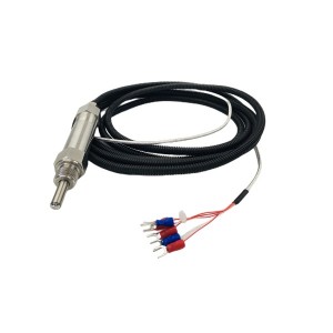
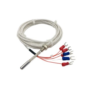
During the operation of the steam turbine, temperature monitoring is the core link to ensure the safety and stability of the equipment. As a key temperature measuring element, the accuracy of the platinum thermal resistance temperature sensor’s signal directly affects the control logic and protection mechanism of the DCS system. When the WZPK2-2212A platinum thermal resistance has a temperature jump in the DCS system, the root cause of the fault must be quickly located to avoid unplanned shutdown of the unit or equipment damage due to misjudgment or delayed processing. Sensor disconnection, dampness of the junction box and signal card failure are common causes of such problems, but there are significant differences in the fault manifestations and troubleshooting logic of the three.
1. Preliminary observation and classification of fault phenomena
When the DCS shows that the temperature value jumps, the characteristics and accompanying phenomena of the jump must be observed first. For example, if the temperature value shows periodic and violent fluctuations, and is accompanied by abnormal signals from other measuring points in the same area, it may involve external interference or signal card problems; if the temperature value suddenly jumps to the upper limit of the range or zero value, accompanied by intermittent alarms, it is more likely that the temperature sensor WZPK2-2212A is disconnected or the line is open. In addition, if the jump phenomenon only occurs under specific working conditions, the contact stability between the sensor and the object being measured or the influence of environmental factors must be considered.
2. Identification and verification of sensor disconnection fault
The disconnection of the platinum thermal resistance WZPK2-2212A is the direct cause of the failure of the temperature signal. Its typical manifestations include the DCS display temperature suddenly rising to the maximum value of the range (such as above 200°C), the value fluctuating violently and then returning to zero, or the instrument continuously alarming to indicate disconnection. The disconnection of the platinum thermal resistance may occur inside the resistor body, at the lead end or at the junction of the junction box. During on-site inspection, the following steps can be taken:
First, disconnect the sensor from the DCS signal line and use a high-precision multimeter to measure the resistance value at both ends of the resistor body. If the resistance value is infinite, it indicates that there is a circuit break in the sensor body or lead; if the resistance value deviates significantly from the nominal value (such as the resistance deviation of a 100Ω platinum resistor at 0°C exceeds ±0.1Ω), it may be that the resistor wire is partially broken or has poor contact. In addition, if the wire break occurs at the junction box end, it is necessary to check whether the terminal bolts are loose or whether there is a virtual connection at the lead welding point.
It is worth noting that some wire break failures may present “intermittent” characteristics, such as poor contact caused by vibration. At this time, it is necessary to repeatedly measure the resistance value in a vibration environment, or use an oscilloscope to monitor the signal waveform to observe whether there is an intermittent open circuit phenomenon. If it is confirmed that the sensor body is damaged, a new component needs to be replaced; if it is a problem with the lead or junction box, the damaged part needs to be repaired or replaced.
3. Detection and treatment of moisture or short circuit in the junction box
The moisture of the junction box of the WZPK2-2212A thermal resistance is an important cause of unstable temperature signals, especially in an environment with high humidity or condensation. After being damp, the insulation performance in the box decreases, which may cause the resistor body to short-circuit with the metal casing, or leakage current between the leads, causing the temperature value to drift or jump. Typical characteristics of this type of fault include: slow fluctuations in temperature values, accompanied by humidity alarms, or increased jump frequency after rain or changes in ambient temperature differences.
When troubleshooting, you need to first check the sealing of the junction box. If cracks are found in the box body, the sealing rubber ring is aged or there are signs of water ingress, it can be preliminarily determined that the seal has failed. For further testing, the sensor needs to be disconnected from the DCS, and a megohmmeter is used to measure the insulation resistance between the resistor and the junction box housing. If the insulation resistance is lower than 10MΩ, there is a risk of short circuit; if the resistance value is close to zero, a short circuit has occurred. At this time, the moisture in the box needs to be cleaned, the sealing material needs to be replaced, and the lead terminals need to be re-welded or crimped. In a humid environment, it is recommended to use an explosion-proof or IP67 protection grade junction box, and regularly check the waterproof performance.

4. Diagnosis and isolation of signal card failure
Signal card failures are often manifested as multiple temperature signals jumping at the same time, or a single signal still being abnormal after changing the channel. The temperature signal card in the DCS system is responsible for converting the resistance value of the thermal resistance WZPK2-2212A into an electrical signal. The noise interference of its internal circuit, the drift of the analog-to-digital converter (ADC), or the power supply fluctuation may cause the output signal to be distorted. The diagnosis of this type of fault requires a combination of hardware status and logic analysis:
First, check the operating status of the signal card through the DCS diagnostic software to confirm whether there is an overload, overtemperature or communication interruption alarm. If the temperature of the signal card rises abnormally or the power supply voltage fluctuates, it is necessary to check its cooling fan, backplane connection and power module. Secondly, the suspected fault channel can be interchanged with other normal channels to observe whether the jump phenomenon is transferred. If the jump migrates with the channel, the signal card fault can be determined; if the phenomenon does not transfer, it is necessary to further check the RTD sensor WZPK2-2212A line or junction box.
In addition, insufficient anti-interference ability of the signal card may also cause jumps. For example, in a steam turbine plant with a complex electromagnetic environment, if the signal line does not use a shielded cable or the shielding layer is not single-point grounded, high-frequency interference may be coupled to the input end of the signal card. At this time, the shielded cable needs to be re-laid, and the physical isolation of the signal loop and the power cable must be ensured. For old systems, you can consider upgrading to an isolated signal card or adding a filter module to improve anti-interference performance.
5. Comprehensive troubleshooting process and preventive measures
For the above three types of faults, on-site troubleshooting should follow the principle of “easy first, difficult later, external first, internal later”. The specific process is as follows:
- • Preliminary isolation: Analyze the jump rule through the DCS historical trend to confirm whether it is a single measurement point fault or a systemic problem. If multiple points are abnormal, check the signal card and grounding system first; if there is a single point fault, focus on the sensor and junction box.
- • Physical inspection: Visually inspect the appearance of the temperature sensor WZPK2-2212A junction box to detect the sealing; gently shake the sensor probe to observe whether it is loose; use an infrared thermometer to compare the temperature of adjacent measurement points to determine whether the sensor is abnormal.
- • Resistance measurement: Measure the sensor resistance value after power failure to determine whether the line is broken or short-circuited; measure the insulation resistance to exclude the influence of moisture on the junction box.
- • Signal comparison: Temporarily connect the faulty sensor to the backup channel, or swap the line with other normal sensors to observe whether the jump is transferred.
- • System verification: After troubleshooting, verify system stability through simulation tests (such as heating sensors or applying interference signals), and record fault characteristics to optimize maintenance strategies.
Although the jump fault of the platinum thermal resistance temperature sensor WZPK2-2212A is complex, through systematic fault tree analysis and hierarchical detection, it can effectively distinguish between sensor disconnection, junction box moisture and signal card failure. This process not only relies on a deep understanding of the equipment principle, but also requires a combination of field experience and standardized operating procedures.
When looking for high-quality, reliable thermal resistance, YOYIK is undoubtedly a choice worth considering. The company specializes in providing a variety of power equipment including steam turbine accessories, and has won wide acclaim for its high-quality products and services. For more information or inquiries, please contact the customer service below:
E-mail: sales@yoyik.com
Tel: +86-838-2226655
Whatsapp: +86-13618105229
Yoyik offers various types of spare parts for steam turbines, generators, boilers in power plants:
Shaft Vibration Sensor probe with Proximity Transducer ES-08-M10X1-3-00-04-10
Flame Detecting Fiber Optic 025OC3100/ST316
Indication AD16-22B/R32/AC380V
TEMPERATURE SENSOR WZP-440
Level Indicator UHZ-10
AC Active/Reactive power (Watt/VAR) transduce S3-WRD-3-015A40N
CIRCUIT BREAKER KFM2-100H/32282
Valve Control Module E1612
Turbine Expansion Sensor TD-2 (0-35mm)
valve 4WRLE 16 V200M-4X/MXY/24A1
TRANSMITTERLIQUID LEVEL UHZ-517-C10AI-2200
Magnetic liquid level gauge UHZ-R000100-1.0-2000
SWITCHGEAR SOCKET YLC1-24A-660V (16/32)
ACQUISITION BOARD GEEBLA-9113
Potensiometer Multiturn WX5-11
Soft start JJR5000-350-380-C
Solenoid valve HSDS-30/V
Cooling tower combine sensor TSM803
RTD SENSOR WZPM2-201-B
Speed sensor CS-1-G-100-03-01
LP Control Valve Position Sensor HL-6-250-15
DIFFERENTIAL PRESSURE SWITCH 101NN-EE3-M4-C1A
Armored Double Channel Pt-100 WZPK2-336S
Oil level gauge KCY-15/16-900/3/10
Smart Temperature Monitor WK-P2T(HT)
Rotation Speed Probe CS-3-M16-L100
Sensor Position LVDT LP bypass 6000TDGN
ZLAB INTELEGENT HUMID CTRL AB-ZWS-41-1S
FTV camera tube SXJZ-70B
Magnetoelectric Speed Sensor Passive D-065-02-01
LVDT Sensor TD-1GN-050-15-01-01
BRAUN MONITOR MODULE E1696.31
TRANSMITTER TEMPERATURE IDCB-4E/DR/Y
Post time: Apr-25-2025
-

TD-2 Steam Turbine Heat Thermal Expansion Sensor
-

ACCUMULATOR BLADDER NXQ 40/31.5-L-E
-

Pressure Switch ST307-V2-350-B
-

Generator Epoxy adhesive DFCJ1306
-

SZC-04FG wall mounted rotational speed monitor
-

SM4-20(15)57-80/40-10-S182 actuator electro-hyd...
-

Servo valve SV4-20(15)57-80/40-10-S451
-

OF3-08-3RV-10 EH oil main tank circulating pump...
-

Oil Water Alarm Level Switch OWK-1G
-

Steam Turbine EH Oil System Servo Valve 072-559A
-

Jacking oil pump filter element HBX-250×10
-

RTD thermocouple temperature sensor probe WZP2-231